Radio construction set “Clone of Lehmann BCL headphone amplifier”
Hi-End clone of Lehmann Black Cube Linear headphone amplifier Due to the ease of repetition, the circuit of this Hi-End class amplifier is popular among radio amateurs. On any amateur radio forum there is a topic about cloning this amplifier. 0. You can buy the original
1. You can completely make a printed circuit board yourself and assemble the amplifier - geektimes.ru/post/257526/ 2. You can buy a printed circuit board in China, fill it with your own parts and get the result - geektimes.ru/post/256990/ Some make homemade amplifiers “cooler” » original - they use cooler details. 3. You can buy a ready-made amplifier - 4. I bought a radio kit: printed circuit board, parts, housing, transformer, connectors, ALPS volume control, etc. I bought from this seller a year and a half ago. From time to time he runs out of these radio sets, he buys them in bulk and sells them further, but he is already opening a new lot on ebay.
Information from the seller
Basic parameters
Frequency range 10Hz-35kHz Adaptation impedance 8-2kΩ Distortion <0.001% (6mW / 300ohm) Output power 200mW / 300ohm; 400mW / 60 ohms. Features power consumption <5W; Input impedance 47kΩ; SNR>95dB; LINE OUT-60ohm; PHONE OUT-5ohm; Channel separation> 70dB / 10kHz. Input Interface RCA connector × 1 group Output Interface: 6.3mm interfaces × 2, RCA Interface × 1 (can be used as preamp) Internal dimensions: Width 135mm height 48mm depth 240mm
main materials:
Opamp is PHI NE5532. Power transistor is ST BD139 140. 30W R-core Transformer. Original ALPS 27 type Potentiometer US CMC Copper RCA Ruby main electrolysis, Siemens MKT coupling capacitors, Panasonic decoupling capacitors, resistors made in TaiWan.
The designer was sent in two parcels:
Included a note:
Photo of the printed circuit board from both sides. High quality PCB:
Power transformer with shield winding:
The circuit diagram of this class A headphone amplifier can be easily found on the internet:
All capacitors and op-amps should be replaced with Wima/Nichichon/Matsushita power filter/OPA2134 instead of the Chinese NE5532.
The transistors of the output stage were selected according to the coefficient. gain.
I soldered it and placed it in the case. The heatsinks of the output transistors were fixed to the printed circuit board using hot-melt adhesive to prevent them from dangling. Signal input and output wires are OFC monocores in the screens. RCA connectors must be isolated from the amplifier body.
There is a special hole on the ULF board for grounding to the case:
I assembled the kit almost a year and a half ago. Now I would install a filter against electromagnetic interference EMI. Like this “1pcs AC2A3-2 Power Line EMI Filter 250V 50/60Hz 3A Brand new”:
Or perhaps into the cable connection socket “CW2A-10A-T-AC-115V-250V-10A-Panel-Mount-3-Pin-Solder-EMI-Filter”:
I fenced off the transformer with an iron screen... The design can be improved ad infinitum...
Setting:
Volume control to minimum. It is better to do the first switching on “through the paw” (a regular 100 W infusion lamp is switched ON CONSEQUENTIALLY to the primary winding of the transformer). Measure the DC voltage between the amplifier output and the common wire at the amplifier output at the output connectors of both channels. If everything is ok: 1. the light does not light, but only perhaps flashes for a second when the power is turned on, 2. the constant voltage is less than 30 mV.
You can turn off the light bulb, plug in headphones and listen to music. If you have an oscilloscope and a signal generator, you can test the amplifier with these devices.
The board has switches for setting a comfortable gain level.
Output DC voltage protection
If “something goes wrong,” the headphones may receive DC voltage. Then the headphones will fail. The original scheme does not provide protection against such situations. I decided to install such protection. The following module with a “green board” is sold on ebay: “Earphone Protection C1237 (UPC1237) DIY Kit” ebay.com/itm/320743978923
I bought it for 300 rubles. Perhaps it is cheaper somewhere. Picture to help. This module is just right for our purposes: 1. If it is “cut” a little on the side of the headphone jack. The headphone jack itself does not need to be installed. The paths here are well located - they do not affect the functionality of the protection. Once isolated from the back of the board, the module fits perfectly above the headphone jacks of the main board. I placed it on plastic M3 racks, drilling the necessary holes. I secured it with plastic nuts and M3 screws. 2. The module’s power supply—bipolar alternating—connected directly to the output terminals of the transformer for ULF headphones. 3. Before installing the ULF on the board, check the circuit. A few seconds after power is applied, the relay should click (the headphones are connected), when DC voltage is applied it should 4. I connected only the signal wires to the protection - the common wire is already connected through the common power wire. The module connected to the gap of the tracks at the ULF output:
It turned out like this:
Measurements
Load: 250 Ohm resistors Vpp=7.2V:
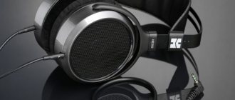
Impression
It sounds good. Neutral. I like. Now the main headphone amplifier. There is no background distortion. The sound is neutral.
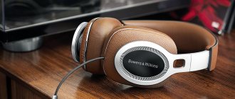
Tested on headphones: Earplugs - Sennheiser CX 300-II (16 Ohm) Beyerdynamic DT 990 PRO (250 Ohm) Everything is ok.
Can be used as a pre-amplifier for a power amplifier. It is also possible to connect 2 pairs of headphones. One plug disconnects the preamplifier output, the other does not disconnect.
The designer himself left an ambivalent impression - on the one hand, an all-in-one set. I bought it, soldered it, everything works, looks beautiful, metal work is kept to a minimum. But modification possibilities are limited by the housing, transformer, and circuit. Which is not good for a DIYer. The high delivery price is apparently due to the weight of the case and transformer. There is no free shipping on these items. Warm up the amplifier - about 20 minutes (the transistors of the output stage heat up to operating temperature). When music plays, the amplifier cools down. When not playing, it warms up. Class A features.
Fourth headphone amplifier circuit, for those “moved” to the tube side
This headphone amplifier circuit (author - B. Kainka, Elektor Electronics magazine, No. 10/2003, p. 70) uses a lamp that was used in radio stations that were once in service with the Soviet Army (R-105M, R- 108M, R-109M and others). And in DOSAAF, such radio stations were used for a very long time - for example, the R-108M was suitable for operating in the 28 MHz range.
Lamp 1P24B - direct filament pentode, rod type, small-sized. The filament voltage indicated in the diagram is 1.2 Volts at a current of 240 mA.
The anode voltage here is low - only 12 Volts, so you don’t have to worry about hundreds of volts coming from the anode circuit.
Headphones are connected directly to the anode circuit, the winding resistance of which must be at least 600 Ohms (they say that there are such “ears” from the “studio” category). And of course, you will need two such lamps - after all, we are supposed to have “stereo”...
The power supply circuit is not given specifically - if you are going to solder this circuit and have found such lamps that are not very common on the market, then in the future you will definitely not need my help in this particular area.
Ultra-linear Class A amplifier
Amplifier version based on domestic transistors
Author: AKA KASYAN
In fact, I didn’t come up with anything new, I just wanted to build this amplifier for a long time, but on many resources the reviews about it were not very good.
Unfortunately, I was unable to find photos of the completed amplifiers. As a rule, there were only discussions on the forum pages and I had no choice but to repeat the design. There are very few reviews about the scheme, mostly only negative. Complaints are mainly about low current consumption, too distorted output signal, etc.
First, all the optimal replacements for transistors were found. All transistors were used domestically. It was not possible to etch the board, so as always, the breadboard came to the rescue.
The entire circuit was assembled on the board, and the output transistors were soldered through wires to the main board. At first I used KT805 transistors for the output stage, then 819 and settled on KT803A - the best option for this circuit.
The circuit was planned for a standard 4 Ohm speaker, so some circuit ratings need to be selected to suit your needs. The output capacitor is 3300 uF with a voltage of 16-50 volts, the input capacitor is to taste (from 0.1 to 1 uF). For power supply I used a battery from an uninterruptible power supply, with it the amplifier develops up to 8 watts, this is pure power, without wheezing, distortion or hum.
During my practice I have collected many power amplifiers. A year ago, the standard of sound for me was STK microcircuits, then the Lanzar circuit was repeated and it did not give up its position for a long time, but a few days ago this amplifier came out on top, leaving the famous Lanzar behind.
A wide range of reproducing frequencies is another advantage of this circuit, although the amplifier will not be able to reproduce frequencies below 30 Hz. The amplifier is designed for wideband acoustics, and for high-quality sound, you first need high-quality speakers. Although many may not agree, I highly recommend using domestic 5 - 10 GDSh heads with a paper or foam suspension. After pure class “A”, even the music center will not sound as good as before.
The output transistors of the amplifier do not heat up as badly as was said in some forums; personally, without a heat sink, they worked for 10 minutes at maximum volume, the temperature did not exceed 70-80 degrees.
The strange thing is that the amplifier is of such high quality that without an input signal there is no noise or hum in the speakers, as if the amplifier is turned off and turns on only when a signal is supplied to the input.
It is not recommended to increase the supply voltage to more than 20 volts; at 18 volts, the amplifier showed 14 watts - pure sinusoidal power, but consumed 60 watts... for class “A” this is quite normal. In the future we plan to build another channel, I really liked this amplifier, even the stereo system sounds bad next to it.
List of radioelements
| Designation | Type | Denomination | Quantity | Note | Shop | My notepad |
| T1 | Bipolar transistor | KT361G | 1 | 2N3906 | Search in the Otron store | To notepad |
| T2 | Bipolar transistor | KT801A | 1 | KT630D, KT602A, 2N697 | Search in the Otron store | To notepad |
| T3, T4 | Bipolar transistor | KT803A | 2 | MJ480 | Search in the Otron store | To notepad |
| C1 | Electrolytic capacitor | 100 µF | 1 | Search in the Otron store | To notepad | |
| C2 | Capacitor | 0.22 µF | 1 | Search in the Otron store | To notepad | |
| C3 | Electrolytic capacitor | 220 µF | 1 | Search in the Otron store | To notepad | |
| C4 | Electrolytic capacitor | 470 µF | 1 | Search in the Otron store | To notepad | |
| C5 | Electrolytic capacitor | 3300 µF | 1 | Search in the Otron store | To notepad | |
| C6 | Capacitor | 0.1 µF | 1 | Search in the Otron store | To notepad | |
| R1 | Resistor | 39 kOhm | 1 | Search in the Otron store | To notepad | |
| R2 | Variable resistor | 100 kOhm | 1 | Search in the Otron store | To notepad | |
| R3 | Resistor | 100 kOhm | 1 | Search in the Otron store | To notepad | |
| R4 | Resistor | 220 Ohm | 1 | Search in the Otron store | To notepad | |
| R5 | Resistor | 2.7 kOhm | 1 | Search in the Otron store | To notepad | |
| R6 | Resistor | 8.2 kOhm | 1 | Search in the Otron store | To notepad | |
| R7 | Resistor | 47 Ohm | 1 | 0.5 W | Search in the Otron store | To notepad |
| R8 | Resistor | 180 Ohm | 1 | 1 W | Search in the Otron store | To notepad |
| R9 | Resistor | 2.2 kOhm | 1 | 0.5 W | Search in the Otron store | To notepad |
| R10 | Resistor | 10 ohm | 1 | 1 W | Search in the Otron store | To notepad |
| Add all | ||||||
Attached files:
- ynch_a.rar (25 Kb)
Tags:
- ULF
- Sprint-Layout
Amplifier power
Power quality is very important for sound. This circuit is designed for bipolar supply voltage. This saves us from having to add unnecessary details to the sound path, and is overall better for the sound.
Today there are op amps operating from ±1.5V, but most opamps operate with a bipolar supply voltage from ±3V to ±18V. The optimal voltage is ±12V or ±15V, which is within the power supply limits of most op-amps.
The exact values of the maximum supply voltage should be found in the documentation for specific microcircuits.
To power the amplifier, it is recommended to assemble a bipolar transformer power supply. To smooth the voltage after the diode bridge, it will be sufficient to install two capacitors with a capacity of 10 μF and 100 - 470 μF.
Voltage stabilization is conveniently implemented on 7812 and 7912 chips.
To ensure good stabilization, it is necessary that the input voltage be at least 2.5-3 volts higher than the stabilization voltage.