Continuity testing of air conditioning compressors
The most common type of compressor in air conditioners is single-phase compressors with a starting winding.
To gain access to the compressor contacts, it is necessary to disassemble the air conditioner so that there is access to the compressor. Usually the contacts are protected by a cover that is screwed in place; you can find it by the wires that go to the compressor. After removing the cover, you will see three contact pins on which terminals with wires are attached.
It is necessary to remove the wires and measure the resistance between the terminals with a multimeter. We set the device switch to the resistance measurement function (indicated by the letter Ω). If the multimeter shows an infinitely large resistance between terminal C and the others, then this means a break; in the case of built-in protection, you need to make sure that the compressor is not overheated and the protection has not tripped; otherwise, and if the external protection is faulty, the compressor is faulty. If the resistance approaches zero, this means a short circuit and the compressor is also faulty.
The exact value of the resistance depends on the power of the compressor, the accuracy of your device and can range from approximately 1-20 ohms.
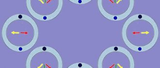
As can be seen from the diagram, the resistance between terminals M and S must be equal to the sum of the resistances between terminals S and C and between M and C.
As a rule, the operating winding (MC) is more powerful, so its resistance is lower than that of the starting winding (SC).
Each compressor has thermal protection, but it can be built-in as in the diagram, or located under the cover, next to the compressor terminals.
If it is not built-in, the so-called “tablet”, then it can be ringed separately and replaced in case of malfunction (it must be closed in the normal state, opens when a certain temperature is reached 90-120 ° C).
I’ll immediately make a reservation that in this way we will not be able to determine short-circuited turns; there are other devices for this (but they also do not detect short-circuited turns stably enough).
Checking the refrigerator compressor yourself
Many people are interested in how to check whether a refrigerator compressor is working or not. It is worth familiarizing yourself with the features of its functioning. It consists of 3 successive stages:
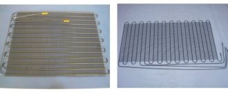
- The principle of operation of the refrigerator motor-compressor is to start a relay that closes the electrical circuit. It turns on when the temperature rises. The supercharger is activated, creating the necessary pressure in the system, and the refrigerant enters the evaporator radiator. Freon becomes liquid and a lot of heat is generated. It is dispersed in the refrigeration chamber using the radiator grille - a coil.
- After passing through the condenser, the gas ends up in the capillary pipeline. There the pressure stabilizes and slowly decreases.
- Liquid refrigerant enters the evaporator at low pressure. It heats up to the desired temperature. The refrigerant turns into steam. The condenser cools and the temperature in the refrigeration unit decreases.
The listed stages form a cycle. It is repeated whenever the temperature rises above a predetermined level. The readings are recorded by a special sensor.
View » What to do when the refrigerator crackles during operation and clicks loudly from behind
You need to prepare the necessary equipment:
- screwdrivers with profiles;
- wrenches 8, 10 and 13 mm;
- pliers;
- multimeter;
- pressure gauge;
- 3 conductor jumpers with terminals;
- electrical tape and rubber or vinyl plugs.
You can replace the screwdrivers with a screwdriver with a set of attachments. It is advisable to use personal protective equipment. The refrigerant may be toxic or explosive. When working with it you need to be extremely careful.
Supercharger malfunction can be due to various reasons. Knowing how the refrigerator works will allow you to determine the breakdown yourself. It is important to consider the type of thermostat.
If it is mechanical, there are 3 reasons for the malfunction:
- relay damage;
- thermostat failure;
- failure of the cold blower.
Resistance check
It is worth checking the resistance of the refrigerator motor with a multimeter. First, it is recommended to find out whether the supply wire is working properly. If it is ok, you need to check the compressor. You should remove the protection unit, remove the contents and disconnect it from the relay. Using a multimeter pliers, you need to measure the wires in pairs. The values must be checked against the table of recommended values for this supercharger model.
Parameters for the usual option between contacts:
- top left and right - 20 Ohm and 15 Ohm;
- left-handed and right-handed - 30 Ohms.
The presence of deviations indicates a breakdown. It is recommended to determine the resistance between the feed-through contacts and the housing part. The infinity sign indicates that the device is working properly. When the tester shows 0 or any other number, there is damage.
Pressure check
When checking the refrigerator for functionality, you need to measure the pressure in the housing. Connect the simulator to the discharge fitting. Take readings with the compressor running. It is considered serviceable when the pressure on the pressure gauge is 6 atmospheres. If the indicator is lower, the housing will need to be replaced.
Current test
After determining the resistance, it is useful to know the current. Connect the compressor relay and motor. Using the tester, clamp the power contact leading to the device. The normal current value is identical to the motor power. For example, at 120 W, 1.1-1.2 A is acceptable.
How to test a relay
To determine the functionality of the refrigerator, you need to know how to check the compressor relay:
- On the tester, turn on the resistance measurement function and remove the protective casing from the relay;
- 3 cables are removed from the body of the pumping device and connected to the main output and winding;
- Connect the pliers in series to the contacts.
The resistance is affected by the modification of the electric motor and the date of manufacture. The acceptable value is 15-40 Ohms. If the value is greater than 10, the motor is broken.
Measuring insulation resistance with a megohmmeter.
A regular tester will not be able to check the insulation breakdown; it measures resistance using a low voltage of 3-9 V. A megohmmeter allows you to measure resistance with a higher voltage of 200-1000 V. But you still need to first “ring” the windings with a multimeter, since you cannot measure resistance with a megohmmeter with a short short circuit of the winding to the housing.
On the device you can select the voltage with which the resistance will be measured and the time during which the windings will be tested.
It is necessary to measure the resistance between one of the three terminals on the compressor and, for example, a copper tube coming out of the compressor with a voltage of 250-500 V. The resistance should be in the range of 7-10 MOhm. If not, then the compressor also needs to be replaced.
Before taking measurements, carefully read the instructions for your device; high voltage is used, so if used incorrectly, you may receive an electric shock or damage the device.
Refrigerator compressor test
In domestic refrigerators, low-power compressors are used, in which the starting winding is connected for a few seconds through a starting relay using a posistor or an electromagnetic relay.
Circuit with electromagnetic relay:
In this case, the current passes in series through the relay coil and the operating winding of the compressor. The starting current is always greater than the operating current, using this principle, the relay is designed so that the starting current closes the relay contacts and connects the starting winding of the compressor, which starts. In this case, the current flowing through the working winding and the relay winding decreases, the contacts open, turning off the starting winding.
The relay also includes a thermal relay that turns off power to the compressor when it overheats.
Circuit with posistor:
In the diagram, the posistor is indicated by the temperature symbol t0, and the thermal relay by the number 6.
The operating principle is as follows: at room temperature, the posistor has low resistance and directly supplies voltage to the starting winding S. A current flows through it, which heats it up; when heated, the internal resistance of the posistor increases, actually turning off the starting winding a few seconds after the compressor starts. The posistor cools down only after turning off the power from the compressor and, during the subsequent switching cycle, reconnects the starting winding.
Tips for checking your refrigerator compressor yourself
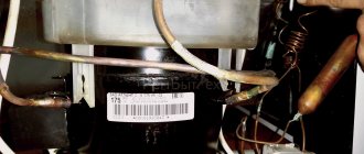
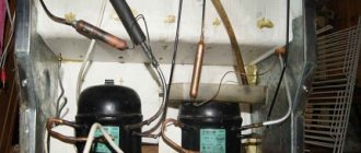
The cylindrical object, usually black, that can be seen on the back side at the bottom of the refrigerator is the compressor casing. A compressor is located inside the casing in transformer oil on an independent spring suspension.
Fundamentally, compressors are no different from each other. They are an electric motor with a piston or plunger injection system. Any AC electric motor has a working and starting winding in its design. A broken or burned wire in one of the windings is the most common cause of breakdown of the entire compressor unit.
Three contact terminals come out of the casing. One of the terminals serves as the output of the starting winding, the other - the working winding, and the third is the common bus.
In addition, each compressor has a start relay. A device for starting a motor in the form of a small box that has a common contact group with the compressor terminals. In other words, this “box” is literally put on these same three terminals. The start relay can also be the reason why the compressor of the refrigeration unit does not start.
The latest models of refrigerators are equipped with fundamentally new compressor starting devices. Such starters are a purely electronic device, unlike the previous electromechanical ones. The analogy with automobile ignition units, which replaced traditional distributors, naturally suggests itself.
Don't forget about the power cable, which we often tug hard on trying to reach the nearest outlet.
Possible faults
From the above reasons, the following list of possible refrigerator malfunctions is formed:
- burnout of one of the compressor windings;
- failure of the starting relay;
- break of one of the current-carrying wires (phase, zero) inside the supply cable.
Consistently eliminating each of the possible faults will allow you to determine the true one and begin repairing or replacing the part.
To check the power cable, it’s a good idea to have a similar one in stock in known working condition. This could be a power cord from an old iron, washing machine, computer power supply and any other devices of suitable power.
It is important to know the functional identity of each terminal and not to confuse the power supply line with the ground bus. Having secured the contacts to the corresponding terminals of the starting relay, we check the functionality of the refrigeration unit. If the compressor starts, the reason is clear.
Another way to check the cable after disconnecting it from the relay is to try to power a simple electrical appliance with it, for example, a table lamp. Here it is important to pre-insulate improvised terminal connections for safety reasons.
Those who have a multimeter in their home arsenal can use this device (if they have experience) to accurately and quickly help determine any possible malfunction.
Checking the starting-protective relays of the refrigerator
Start-protective relays look like this:
Electromagnetic relay
Relay with posistor
The round black “pill” with terminals is a thermal relay that is closed at normal temperatures and opens only when very hot. It is checked with an ohmmeter - the resistance should tend to zero, or in the “continuity” mode - there should be a sound signal when the probes are applied to the terminals.
The same applies to the posistor - in the normal state it is closed. It is usually located inside the relay, between terminals S and R of the compressor. (In the picture above, these are terminals on a white base).