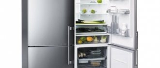
The most necessary appliance, both in an apartment and in a private house, is a refrigerator. And it’s hard to disagree with this statement, isn’t it? It's difficult to find a home that doesn't have one. Like any appliance, refrigerators can break down. But there are situations when a breakdown can be diagnosed independently.
Almost all household refrigeration equipment is equipped with a single-phase motor. To start it you have to use a starting device. If this simple but important part fails, the compressor will no longer start. But, knowing the principles of operation of the device, you can identify the problem and fix it.
This article will talk about how the start relay for a refrigerator works and the signs of its malfunction. We will tell you how to troubleshoot refrigeration equipment. The videos we present will help you understand the principle of operation of the starting device, and also, if necessary, identify its malfunction.
Starting a single-phase asynchronous electric motor
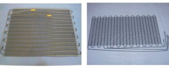
At their core, compressor motors installed in modern refrigerators are single-phase asynchronous electric motors with a starting winding. Their main components are a rotating rotor and a stationary stator.
The rotor is a hollow cylinder made of conductive material or containing short-circuited wiring.
The stator includes two windings: working (main) and starting (starting). They are mutually located at an angle of 90 degrees, or have the opposite direction of winding - the so-called “bifilar”. Alternating current passing through the main winding creates a magnetic field with a changing vector.
The pulsating field can be decomposed into two, rotating with the same period, but in opposite directions. This makes it easier to understand the physical essence of the process of influencing the rotor
If the rotor is not static, then, according to the law of electromagnetic induction, the motor will develop or decelerate torque, since the slip relative to the forward and reverse magnetic flux is different. Therefore, to maintain movement, alternating current passing through the working winding is sufficient.
If the rotor is stationary, then with the same slip relative to the magnetic fluxes, the resulting electromagnetic torque will be zero. In this case, it is necessary to create a starting torque. This is why a starting winding is needed.
The currents in the windings must be phase shifted, so a phase-shifting element is introduced into the motor - a register, inductor or capacitor. After the rotor reaches the required rotation, the supply of electricity to the starting winding stops.
Thus, to start a single-phase asynchronous electric motor, current must pass through two windings, and to maintain rotor rotation, only through the working winding. To regulate this process, a start relay is installed in the circuit in front of the refrigerator compressor.
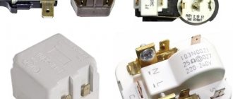
The relay is located close to the compressor and in such a way that it can be easily removed. It is with checking this unit that one begins when the engine is running problematically.
Causes of failure
Often the cause of failure is due to natural wear and tear of certain elements of this part or generally incorrect operation of the equipment.
There are 2 main signs of malfunction of this particular refrigerator element:
- The motor of the device turns on, but after a short time it turns off, or does not start at all. It is likely that the contacts in the winding have shorted out.
- The engine does not start, but current flows to it. A possible reason is a weakened spring, which requires prompt replacement of the starting relay.
Read more: How to start renovating a room
Operating principle of the start relay
Despite the large number of patented products from various manufacturers, the operation schemes of refrigerators and the operating principles of starting relays are almost the same. Having understood the principle of their operation, you can independently find and fix the problem.
Device diagram and connection to the compressor
The relay circuitry has two inputs from the power supply and three outputs to the compressor. One input (conditionally zero) passes directly.
The other input (conditionally – phase) inside the device is split into two:
- the first passes directly to the working winding;
- the second passes through the disconnecting contacts to the starting winding.
If the relay does not have a seat, then when connecting to the compressor you must not make a mistake with the order of connecting the contacts. Methods common on the Internet for determining winding types by measuring resistance are not correct in general, since some motors have the same resistance of the starting and running windings.
The electrical circuit of the start-up relay may have minor modifications depending on the manufacturer. The figure shows a diagram of the connection of this device in the Orsk refrigerator
Therefore, it is necessary to find documentation or disassemble the refrigerator compressor to understand the location of the feed-through contacts.
This can also be done if there are symbolic identifiers near the outputs:
- “S” – starting winding;
- “R” – working winding;
- “C” – general output.
The relays differ in the way they are mounted on the frame of the refrigerator or on the compressor. They also have their own current characteristics, so when replacing it is necessary to select a completely identical device, or better yet, the same model.
Closing contacts using an induction coil
An electromagnetic starting relay works by closing a contact to pass current through the starting winding. The main operating element of the device is a solenoid coil connected in series with the main winding of the motor.
At the moment the compressor starts, with the rotor static, a large starting current passes through the solenoid. As a result, a magnetic field is created that moves the core (armature) with a conductive strip installed on it, which closes the contact of the starting winding. The rotor begins to accelerate.
As the rotor speed increases, the amount of current passing through the coil decreases, as a result of which the magnetic field voltage decreases. Under the action of a compensating spring or gravity, the core returns to its original position and the contact opens.
On the cover of the relay with the induction coil there is an “up” arrow, which indicates the correct position of the device in space. If it is placed differently, then the contacts will not open under the influence of gravity
The compressor motor continues to operate in the mode of maintaining rotor rotation, passing current through the working winding. The next time the relay will work only after the rotor stops.
Regulation of current supply with a posistor
Relays produced for modern refrigerators often use a posistor - a type of thermal resistor. For this device, there is a temperature range below which it passes current with little resistance, and above which the resistance increases sharply and the circuit opens.
In a starting relay, a posistor is integrated into the circuit leading to the starting winding. At room temperature, the resistance of this element is insignificant, so when the compressor starts operating, current flows unhindered.
Due to the presence of resistance, the posistor gradually heats up and when a certain temperature is reached, the circuit opens. It cools down only after the current supply to the compressor is stopped and starts skipping again when the engine is turned on again.
The posistor has the shape of a low cylinder, which is why professional electricians often call it a “tablet”
Implementation of current type protection
An asynchronous motor is a complex electrical device that is prone to breakdowns. If a short circuit occurs, the circuit breaker installed in the distribution panel will trip.
If the fan, which cools the winding and mechanical moving elements, fails, the built-in thermal protection of the compressor will react.
The internal thermal protection of the electric motor is based on posistors. It responds to a general change in temperature inside the device, which can have both internal and external causes.
However, a situation may arise when the motor begins to consume 2-5 times more rated current for a long time (more than 1 second). Most often this occurs when there is an unplanned load on the shaft resulting from a jammed motor.
The current increases, but does not reach the short circuit values, so the machine selected for the load will not work. There is also no reason for the thermal protection to turn off, since the temperature will not change in such a short period of time.
The only way to quickly respond to the situation and avoid melting of the working winding is to trigger the current protection, which can be installed in different places:
- inside the compressor;
- in a separate current protection relay;
- inside the start relay.
A device that combines the functions of turning on the starting winding and current protection of the motor is called a starting protection relay. Most refrigerator compressors are equipped with just such a mechanism.
The action of current protection is based on three principles:
- as the current increases, the resistance decreases and the heating of the conductive material increases;
- under the influence of temperature, the metal expands;
- The thermal coefficient of expansion differs for different metals.
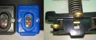
Therefore, a bimetallic plate is used, which is welded from metal sheets with different expansion coefficients. Such a plate bends when heated. One end of it is fixed, and the other, deviating, opens the contact.
To heat a bimetallic circuit breaker, a coil is usually placed nearby through which electricity passes. Although sometimes they implement a “direct” version in the form of a conductive plate
The plate is designed for a temperature response when a current of a certain strength passes. Therefore, when replacing the start-up relay, it is necessary to check its compatibility with the installed compressor model.
Troubleshooting
Given the small number of relay elements, you can sequentially test them for functionality. To do this you will need a flathead screwdriver and a multimeter.
No. 1 - problems with relay operation
From a design point of view, a relay with a coil is a device with normally open contacts, and a posistor version is a device with normally closed contacts. Although in both cases there are possible options when, at start, there will be no current supply to the starting winding or, conversely, its shutdown will not work.
If the compressor is operational, but does not turn on following a command sent from the refrigerator control unit, this indicates a lack of voltage on the stator starting winding.
The reason for this may be:
- electrical circuit break;
- contact strip problem;
- posistor overheating;
- the electrical protection system is triggered and does not return to its normal position.
If the refrigerator turns on for 5-20 seconds and then turns off, then most often this is a consequence of the relay’s protective mechanism triggering.
The reasons may be the following:
- the protective mechanism is working properly, but the operation occurs due to problems in the working winding of the motor;
- the protective mechanism is working, but the relay does not open the contacts in the starting winding circuit;
- The protective mechanism is faulty, false operation occurs when the temperature is slightly overheated.
Since there may be several reasons for the malfunction, it is necessary to carry out a complete diagnosis of the start-up protection relay of the refrigerator.
The cost of start-up protection relays for brands such as Atlant or Biryusa does not exceed 500 rubles. If you quickly purchase and install a new working device, the refrigerator will not even have time to defrost
No. 2 - faulty electrical circuit contacts
A faulty start-up relay can be detected using a multimeter.
To do this, you need to ring three sections of the electrical circuit:
- If there is a break in the area from the input to the output to the working winding, then it is necessary to check the location of the contact opening with the protective mechanism. It is possible that it worked and did not return to its original state or that the opening contacts were oxidized.
- If there is no contact in the area from the input to the output to the starting winding, then in addition to a banal break in the conductor, two options are possible: opening the circuit by a protective mechanism or lack of contact through the bar.
- A break in the straight (zero) section means mechanical damage to the chain - it is the easiest to find and fix.
If the relay operation is based on the use of an induction coil, then it is necessary to forcibly raise the bar - otherwise there will be no contact.
Using a multimeter, it is easy to detect faulty contacts by testing them through a resistance. It is important to take your time and check each section of the chain one by one.
No. 3 - incorrect operation of the posistor
To make sure that the posistor is working properly, you need to check it in a cold and heated state.
First of all, you need to wait until the posistor has cooled down (2-3 minutes in a non-working state is enough) and ring it with a multimeter. If there is no current or a high resistance is detected, the posistor is faulty and needs to be replaced.
If the device is working properly, then when checking it in a cold state, the multimeter should show the presence of slight resistance
To check the disconnection ability, you need to connect a consumer of electricity, for example, a hundred-watt incandescent lamp, to the posistor. To do this, you need an electrical plug with two terminals that are connected to the input of the device. The wires from the lamp are connected to the connectors leading to zero and the starting winding.
When the plug is plugged into the socket, the light will light up. Since the rating of the passing current in the experiment is significantly less than when starting the compressor, the posistor will heat up for a long time - for a hundred-watt lamp the response time will be 20-40 seconds.
If the light goes out after a while, then the device is working properly. If the consumer is not de-energized, this means that the posistor is not working. Repairing it at home is impossible, it is inexpensive, so you need to purchase an element with similar parameters.
No. 4 - problems with the contact strip
There are two types of contact strip problems:
- no current passes when the contacts are closed;
- The bar sticks and won't go down.
The first problem may arise due to oxidation of contacts. In this case, you need to clean them with sandpaper. Also, the reason may be the curvature of the position of the bar, then it is necessary to install it horizontally.
To clean the contacts and remove dirt or traces of oxidation, you can use fine sandpaper by placing it on a needle or thin flexible awl
A more difficult problem is the junction of the bar and the pin, which is affected by the magnetic field of the solenoid. The solution to the problem here is individual and depends on the type of malfunction.
Sticking of the strip is expressed in the fact that it does not come off along with the core. To do this, you need to clean the contacts to remove the adhesive and make them smooth.
No. 5 - abnormal operation of current protection
If, when ringing, a lack of contact is detected from the input to both windings, then most likely the break occurred in the protection zone.
In most cases, this is either a contact failure that opens the bimetallic plate, or damage in the area of the heating coil.
The bimetallic plate and its heating coil must not be bent, displaced or otherwise carried out with them that would cause a change in the configured operation mode
If the damage cannot be corrected otherwise, you will have to purchase a new relay.
Operating principle of the starting protection relay
The starting coil must be turned off when the speed is up. At the moment of start, the windings consume a large current, the effect allows you to track the moment of recommutation. The refrigerator start relay performs protective functions (not always). The option is implemented by heating the sensitive element with electric current. The threshold is exceeded - the circuit breaks, regardless of whether the desired refrigerator mode has been reached according to the thermostat readings or not. Two schemes for the operation of the starting relay have been invented (at the same time it can be protective):
- "Tablets" work on the basis of a material that expands by heat. Initially, the working element is cold, the starting winding consumes current, ensuring a smooth start of the asynchronous motor. Gradually, the temperature of the tablet rises, causing the contact to open, and the working coil remains switched on. We believe that to maintain the mode, a mechanism is installed inside the relay to prevent the tablet from cooling. Operating winding choke, heating element. If a button relay breaks, you can often hear the rustle of scattered powder inside, changing the position of the device body.
- Induction relays are based on the action of electromagnets. When starting, the current is high and due to this the core presses the contacts of the starting coil. Over time, engine consumption drops. As a result, the current will no longer balance the spring, and the contacts of the starting coil open. Please note: it is important to orient the relay in space correctly. Often the core falls, carried away by the force of gravity. But testing such elements is much simpler: turn from side to side so that the contacts of the starting relay change the resistance from zero to infinity.
The tablets often come with thermal relays on a bimetallic plate in the same housing. The current of the working coil passes through it. As soon as the value exceeds the response threshold, the contacts open, stopping the compressor. The bimetallic type refrigerator relay circuit is based on heating the sensitive element.
There is nothing complicated about it! The two plates are welded tightly to each other. The coefficient of expansion of metals in them is different. When heating occurs, the double plate bends towards the material that elongates less. It becomes possible for the relay to operate. This scheme is often used in household appliances.
Induction relays often use a heating coil. There is already one material here. But it heats (!) the bimetallic plate. The current of the working coil passes through the spiral. If the amperage is too high, the bimetallic strip breaks the contacts. The inductive start-up relay has the following types of faults:
- the spiral has burned out, in this case the contacts will not ring in any position;
- the core is jammed, the engine does not start, or the engine stalls after 5 - 10 seconds;
- The operating mode of the plate is disrupted, the refrigerator turns off even in normal mode.
We would like to draw your attention: thermal protection is completely emergency. In normal operation, the relay should not operate. At the same time, the starting function accompanies the refrigerator during the operating period. The switching process is accompanied by a slight click. We often hear the start-up relay in the refrigerator when the appliance is running.
The start-up relay resembles a tablet or an indeterminate shape in appearance. This is such a small element located directly next to the black barrel-shaped compressor housing. Have you ever wondered why this soot color was chosen to paint the heart of the refrigerator?
The answer is simple: black absorbs heat, but also radiates well. In which direction the process moves determines the direction of the temperature difference between the compressor and the environment. When the motor is hot, the black housing gives off heat to the air. In addition, there is a fan nearby that creates forced cooling of the compressor.
Read more: Water pressure switch, operating principle, setup and adjustment
Switching diagram of the refrigerator start-up relay:
- Phase 220 V.
- Earth.
- Starting winding of an asynchronous compressor motor.
- Working winding of an asynchronous compressor motor.
- Earth.
You can usually find out what is connected where and by the color of the wires. In any case, repairs should be carried out carefully. It’s easier to find out the compressor ground if you scrape a little paint off the housing and ring the three contacts. But this method is left for last when the others have not helped.
DXR induction start-up protection relays are mounted on a fixed frame and work in tandem with DXM compressors. The designation may be followed by a number that is the same for both devices. The difference in designs is in the operating voltage and operating and releasing currents. To speed up the breaking of the circuit when overheated, a magnet is located behind the bimetallic plate.
The induction relay for the RTP refrigerator compressor differs in that it can also be located on a wire. Doesn't have to be attached to the frame. The work is carried out with compressors DXM 3 and 5. The difference from DXR is a slightly lower operating current. This will better protect the compressor. The release current is the same. Craftsmen use refrigeration compressors to manufacture high-pressure apparatuses and receivers. Tires are inflated and pneumatic equipment is used.
Before you buy a relay for your refrigerator, make sure that the product matches the type of compressor. The element must then be installed correctly. It is better to take exactly the brand that was available before the repair. If the relay of the Biryusa refrigerator is equipped with the RTK type, it is better to take this, despite the fact that both RTP and DXR are also suitable for the DXM engine. Lookup tables can help determine device compatibility. Indicate the necessary technical information.