Apr 13
There are a lot of descriptions on the Internet about how to connect a universal scaler to a matrix, but there was no detailed diagram of the complete connection. And if there is, it is very difficult to find. Everything has to be compiled from 2-3 articles. It was decided to make a full description based on our own connection.
There were 2 monitors lying around in the closet, 17″ and 19″. One showed only blue, the second only green. Both matrices are live, just for experiments with the scaler.
First sample: Samsung 940n,
with matrix - HSD190MEN3
Second sample: Proview ma782Kc,
with matrix - PV170LCM
Purchased universal scaler: model - LA. MV29.P.
The diagram according to which we connect this work of Chinese engineers:
Monitor power supply - monitor inverter - scaler - matrix - buttons - speakers.
Apart from the scaler itself, nothing was bought: no cables, no buttons, no inverters.
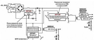
Connecting the power supply and monitor inverter to the scaler.
Everything here is so simple that it even became somehow sad ((
All you need to do is connect: power to the scaler, control of the inverter and the brightness of the lamps.
We need 4 contacts: plus, minus, contact for turning on the inverter (backlight lamps) and controlling the intensity of the lamps. On the power supply itself these are the contacts:
BLON
- everything that is written ON is turning on the inverter.
BRI
- brightness control, often referred to as
DIM
.
+14V
- it’s clear that it’s + power supply, but don’t forget that we have a scaler of 12 - it needs to be lowered, more on that later.
GDN
- minus (ground).
Where should I solder all this on the scaler?
Scaler contacts and signal matching.
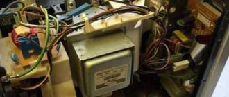
We find the inverter connector itself.
And according to the marking we connect.
Don’t forget that 14 volts is a lot of power for a scaler; I recommend installing a voltage stabilizer at 12 volts (for example, L MC 7812
) into the power supply section (any other 12 volt can be used, according to its connection diagram). In my case, the connection diagram for the stabilizer is as follows:
Power bank from a broken laptop
If your old laptop turns out to be unusable, then disassemble it into parts. Some laptop components can be adapted to upgrade your PC. For example, install a hard drive from a laptop into the PC system unit.
And the battery can be used to make an excellent portable charger (Power bank). Perhaps this power bank will not be as compact as a store-bought one, but in terms of battery capacity (and, therefore, in the number of times your smartphone or tablet can be charged), it is in no way inferior.
And here's how to make a power bank from a laptop battery (you'll need a soldering iron and some knowledge of electronics!):
Don’t want to deal with assembling and soldering all sorts of things from an outdated laptop? Then there is only one thing left...
Connecting the matrix to the scaler.
In fact, I was lucky and my connection to both matrices was identical. I just had to disassemble the 17″ monitor cable and simply rearrange the contacts. The inputs to the matrix are also identical, in the end I tested 2 matrices of different monitors at once with one cable.
Connector and symbols on the matrix.
You can see 10 channels, the power supply is 5 volts and the gaps between the channels are massive.
Scaler connector.
Tryndets, this is where I got into a stupor. There is not a single marking on this connector.
It’s good that there are kind people who posted another version of the scaler with exactly the same pinout.
Everything on the cable from the matrix to the original scaler is mixed up. Need to fix it)
| Frequent designation | My matrix | Universal Scaler |
| LCD-VDD power supply for panel | VDD+5V | VLCD |
| LCD-VDD power supply for panel | VDD+5V | VLCD |
| LCD-VDD power supply for panel | VDD+5V | VLCD |
| GND Ground | GND | GND |
| GND Ground | GND | GND |
| GND Ground | GND | GND |
| RXO0-LVDS ODD 0 - Signal | RA_NO | BTXO- |
| RXO0 + LVDS ODD 0 + Signal | RA_PO | BTXO+ |
| RXO1-LVDS ODD 1 - Signal | RB_NO | BTX1- |
| RXO1 + LVDS ODD 1 + Signal | RB_PO | BTX1+ |
| RXO2-LVDS ODD 2 - Signal | RC_NO | BTX2- |
| RXO2 + LVDS ODD 2 + Signal | RC_PO | BTX2- |
| GND Ground | GND | GND |
| GND Ground | GND | GND |
| RXOC-LVDS ODD Clock - Signal | RCLK_NO | BTXC- |
| RXOC + LVDS ODD Clock + Signal | RCLK_PO | BTXC+ |
| RXO3-LVDS ODD 3 - Signal | RD_NO | BTX3- |
| RXO3 + LVDS ODD 3 + Signal | RD_PO | BTX3+ |
| RXE0-LVDS EVEN 0 - Signal | RA_NE | ATXO- |
| RXE0 + LVDS EVEN 0 + Signal | RA_PE | ATXO+ |
| RXE1-LVDS EVEN 1 - Signal | RB_NE | ATX1- |
| RXE1 + LVDS EVEN 1 + Signal | RB_PE | ATX1+ |
| RXE2-LVDS EVEN 2 - Signal | RC_NE | ATX2- |
| RXE2 + LVDS EVEN 2 + Signal | RC_PE | ATX2+ |
| GND Ground | GND | GND |
| GND Ground | GND | GND |
| RXEC-LVDS EVEN Clock - Signal | RCLK_NE | ATXC- |
| RXEC + LVDS EVEN Clock + Signal | RCLK_PE | ATXC+ |
| RXE3-LVDS EVEN 3 - Signal | RD_NE | ATX3- |
| RXE3 + LVDS EVEN 3 + Signal | RD_PE | ATX3+ |
This is how it happened for me.
Option to check.
The final version.
On the matrix, the two left power +5 are inserted first, then the red one is in the middle, this is common. If you turn the matrix over, you can see that they go to ground.
For control, I connected only the general and power supply, and turned on the scaler. It immediately became clear that the matrix was working, it immediately turned black
. Without power, when only the lamps work, it is brighter.
Theoretical part
The display will be attached to the monitor in place for a VESA mount and stick out from the side like an ear. It weighs quite a bit, which means the monitor will skew. To avoid distortion, you need to add a counterweight on the other side. After weighing and measuring everything, this is what I got:
42cm * 920gram + 28cm * 210gram = 24cm * Xgram X
= 42cm * 920gram + 28cm * 210gram / 24cm
=
1855gram
This is the figure I was guided by when assembling the counterweight. I took coins from scrap materials for counterweight.
Using an old laptop: TV, kitchen computer, arcade machine
If a laptop is so old that it can't handle games and other modern tasks, then it can be turned into a highly specialized device aimed at tasks that do not require high performance. For example, an outdated laptop will make a good alternative to a small wall-mounted TV, and you can do it yourself:
If you or your loved one loves to cook, then make her a kitchen computer in which recipes will be stored. It’s good if the device still has Internet access. Also, do not forget about the program in which timers are set. Here is an example of such a homemade machine:
If you are an avid old-school gamer who remembers the era of 8-bit games , then why not build your own arcade machine?
Or simply use an old laptop as a digital photo frame hung on the wall:
Practical part
Display
The display from the laptop was removed along with the case and hinges (it seems to be more aesthetically pleasing). There is a limiter on the hinges for opening the laptop lid and it really bothers us, since now they will be open at angles greater than 140 degrees. The limiter is a protrusion in the frame. You can either grind it off or hammer it back in, which is what I did. Next, having made a housing for the LCD controller from the housing from the power adapter (yes, I disassembled the power adapter), I attached the whole thing to the back side of the display with a glue gun. This was the end of the display.
Frame
We assemble a square from a 28x27 profile.
This is necessary firstly because the display hinges and the 60x27 profile are attached to opposite sides of the square. And secondly, to increase the thickness of the metal for the threads for the bolts. The profiles are fastened together into a square using a riveter, then threads are cut for the bolts. In the 60x27 profile we make 2 holes for a VESA mount (I have it VESA MIS-D, 100, C - that is, the holes are 10 cm apart) and fasten it with rivets to a previously made square.
power unit
The power supply case was disassembled for subsequent placement of the power supply inside the 60×27 profile (it did not fit with the case)
I made a replacement body (as insulation) from cardboard and glued it to the profile with a gun. The power supply itself is glued at the corners to the cardboard.
In the end, I got this “shovel”.
Installation and connection
We fasten the “shovel” to the main monitor with bolts (left over from some furniture) on VESA.
We attach a counterweight. Connect DVI and power. The display was not immediately detected. Go here: Control Panel → Display → Screen Resolution Settings → Find
and customize it to suit your needs. All! Our second monitor is ready!
How to make a TV from a monitor with your own hands: via hdmi, wi-fi, with a set-top box, instructions
You can convert any display into a TV, but the only condition is that the device must have a VGA input. The tuner does not have to be placed inside the case; it is enough to attach it on top. So, here are 5 ways to convert a regular monitor into a TV:
Adapters
HDMI adapter and VGA input. The devices will be connected to each other using a special adapter wire with plugs - a regular one and a VGA port.
Smart TV
Smart TV set-top box . This method is considered the best in terms of functionality, since you can not only watch TV shows, but also use applications and play games. The only thing is that such a device will have to be connected to the Internet. You also need to stock up on a special adapter for transferring HDMI-VGA images.
Worth knowing: With this connection, you will have to transmit sound over another channel, since VGA is not designed to transmit audio signals.
Therefore, if you don’t want to bother with multiple channels, and don’t mind paying a little extra money, it’s better to buy an HDMI-VGA-MiniJack adapter. You can connect speakers to it and then there will be no problems with sound transmission.
TV tuner
TV tuner . This device is a full-fledged TV, but without a display. To complete the package, simply connect a monitor to the tuner and get a real TV with all its functions. The price of such a device is small, and you can choose whether to pay less or more for such a device. The thing is that there are 4 types of TV tuners:
- Built-in block . It needs to be installed into the system. It’s difficult to do on your own, without special skills.
- External block . Connects using ExpressCard.
- Network tuner . A router is used to connect.
- Tuner console . A stand-alone device that is connected via a wire.
To operate the first three types of devices, you will need the technical stuffing of a PC, since they are just an addition. Therefore, it is better to purchase a device that is autonomous and has its own board. To connect, you just need to connect both devices using an RCA cable. You can control channel switching, sound and other parameters using the remote control that comes with any tuner model.
Important to know: If your receiver does not have speakers, then you should connect speakers. There is an audio output for this, or stock up on a regular mini-Jack adapter.
To be able to watch digital TV, you will also have to buy a special receiver that has an RCA output, as well as HDMI and VGA.
Wires for setting
Smartphone, iPad. Both online TV and any other content will be perfectly displayed from a mobile gadget. To do this, buy an HDMI cable and an adapter for the gadget. Connect like this:
- Set up your monitor and gadget for an HDMI source.
- Connect the two devices with adapters and wires.
- Select the desired resolution.
You can create such a design using an adapter and a VGA interface. Once you have everything you need, do the following:
- Place all components on the table surface. Connect them using cables.
- Connect the gadget to the network.
- Also install speakers nearby and connect them using a mini-Jack.
It is very convenient if you download your favorite movie or TV series to your gadget in advance, and then, using a simple design, enjoy watching it on the big screen. This method is the cheapest and easiest.
Laptop monitor as TV
Laptop. You can use your laptop or PC to watch TV shows over the Internet. IPTV technology helps with this. To watch TV broadcasts, do the following:
- Download and install an IPTV player on your laptop.
- Also download a playlist with channels on the Internet.
- Upload the downloaded playlist to the player in the “Channel List” .
- Click Save .
Interesting: You can watch several channels at once. This function is supported by modern IPTV players.
Flaws
- Not a very good matrix. Firstly, it is glossy and because of this it glares. Secondly, the viewing angles are not very good (Thankfully, the hinges have not lost their ability to rotate the display to the desired angle).
- Due to the difference in aspect ratio of the displays (the main one is 1920x1080, the second one is 768x1360), there is no effect of a single display. Yes, I made the resolution 768x1024 - much better with solidity, but I was not satisfied with the quality of the picture (the letters floated a little).
- My profile design is not very good because... it has poor resistance to torsion, which arises due to its characteristics and the way loads are applied to it. This problem can be avoided by attaching a second profile to the bottom two VESA mount holes and riveting everything into a rigid structure.
By the way:
I don’t know whose fault this is, but when I connected my display to the VGA output of the Samsung R519 laptop under Xubuntu, the colors on the display were very strange.
conclusions
Another “project” has been completed and the final result has been obtained.
The total cost of the design with the price of a matrix of 1000~1500, a controller of ~900 rubles, a power supply with a cord of ~400 rubles and consumables of 50~100 rubles is 1950~2500 rubles. For this money (well, maybe adding a little) you can buy a completely sane second monitor. I got a second display for practically nothing (after spending only 25 rubles on a small drill and 150~200 rubles worth of coins). I had everything else one way or another. It was only necessary to rummage through the drawers of the desk. If I had to do it a second time, I would use aluminum corners or squares.