Measuring equipment and repair tools
To determine how to repair LCD TVs and other models, you first need to determine the cause of the breakdown. To do this you will need the following equipment:
- tester or multimeter - for determining voltages at special (control) points, measuring resistor and capacitor values, testing circuits and parts (coils, transformers, diodes, etc.);
- amplifier - to determine where the sound signal disappears;
- oscilloscope - for comparing signals at certain points with the TV circuit. It is used quite rarely at home, since not everyone knows how to work with it.
Regardless of the malfunction, you will need the following equipment to repair TVs:
- screwdrivers of different sizes (straight, Phillips, rarely asterisks);
- “hexagons” – quite rare, but necessary;
- pliers, wire cutters, etc.;
- soldering iron (25-60 watts) with rosin and tin;
- hair dryer or soldering station - for modern models with a flat screen.
- schematic diagram of the TV unit (can be found on the Internet). For example, the diagram of LCD devices looks like this:
Getting started - troubleshooting
A special troubleshooting technique has been developed for beginners, which will help them navigate when carrying out repairs. The table provides a description of the main faults and instructions in which unit the TV should be inspected and repaired.
| What's happening | Possible reason |
| The device does not turn on | Power supply, power button, cord |
| The LCD screen does not light up, there is an image, but barely noticeable | Lamps or backlight diodes, their power supply |
| No sound, TV wheezes | Sound amplifier or harness (microcircuit and parts around it) |
| The screen is lit, but the TV does not show | Receiving unit (tuner and its circuits), video processor |
Please note that if, during a visual inspection, you find darkening on the board, carbon deposits, swelling or rupture of parts, then you cannot immediately replace the damaged elements. A burnt component may be a sign of a short circuit, but the cause will be in a completely different direction.
Important! When inspecting, be sure to unplug the TV.
TV repair - troubleshooting technique
Finding a defect is much more difficult than eliminating it, especially for a novice master. The universal method proposed by the author of the article will allow you to quickly and effectively diagnose a modern TV.
WHERE TO START
When repairing television receivers, there are situations when the TV does not turn on and does not show any signs of life. This makes it much more difficult to localize the defect, especially considering that imported equipment often has to be repaired without schematic diagrams. The technician is faced with the task of identifying the malfunction and eliminating it with the least amount of time and effort. To do this, you need to follow a certain troubleshooting technique.
If a workshop or private master values its reputation, it is necessary to start with cleaning the device. Armed with a soft brush and a vacuum cleaner, you should clean the inner surface of the case, the surface of the kinescope and the board of the television receiver. After thorough cleaning, an external inspection of the board and elements on it is carried out. Sometimes you can immediately determine the location of the malfunction by swollen or ruptured capacitors, by burnt resistors, or by transistors and microcircuits that have burned through. It happens that after cleaning the kinescope from dust, instead of a transparent bulb, we see a milky white inner surface (loss of vacuum).
Much more often, a visual inspection does not reveal external signs of faulty parts. And here the question arises - where to start?
POWER UNIT
It is most advisable to start repairs by checking the functionality of the power supply. To do this, turn off the load (horizon output stage) and connect a 220 V, 60...100 W incandescent lamp instead.
Typically, the horizontal scan supply voltage is 110...150 V, depending on the size of the kinescope. Having looked at the secondary circuits, on the board next to the pulse transformer of the power supply we find a filter capacitor, which most often has a capacity of 47...100 μF and an operating voltage of about 160 V. Next to the filter there is a horizontal scan supply voltage rectifier. After the filter, the voltage is supplied to the output stage through a choke, a limiting resistor or a fuse, and sometimes there is simply a jumper on the board. Having unsoldered this element, we will disconnect the output stage of the power supply from the horizontal scanning stage. We connect an incandescent lamp in parallel to the capacitor - a load simulator.
When turned on for the first time, the key transistor of the power supply may fail due to a malfunction of the wiring elements. To prevent this from happening, it is better to turn on the power supply through another 100...150 W incandescent lamp, used as a fuse and switched on instead of the soldered component. If there are faulty elements in the circuit and the current consumption is large, the lamp will light up and all the voltage across it will drop. In such a situation, it is necessary, first of all, to check the input circuits, the mains rectifier, the filter capacitor and the powerful transistor of the power supply. If, when turned on, the lamp lights up and immediately goes out or begins to glow faintly, then we can assume that the power supply is working, and it is better to make further adjustments without the lamp.
Turn on the power supply and measure the voltage across the load. Look carefully on the board to see if there is a resistor for adjusting the output voltage near the power supply. Usually next to it there is an inscription indicating the voltage value (110...150 V).
If there are no such elements on the board, pay attention to the presence of control points. Sometimes the supply voltage is indicated next to the terminal of the primary winding of the line transformer. If the diagonal of the kinescope is 20…21″, the voltage should be in the range of 110…130 V, and if the kinescope size is 25…29″, the supply voltage range is usually 130…150V.
If the supply voltage is higher than the specified values, it is necessary to check the integrity of the elements of the primary circuit of the power supply and the feedback circuit, which serves to set and stabilize the output voltage. Electrolytic capacitors should also be checked. When dry, their capacity decreases significantly, which leads to incorrect operation of the circuit and an increase in secondary voltages.
For example, in an Akai CT2107D TV, when the electrolytic capacitor C911 (47 µF, 50 V) dries out, the voltage in the secondary circuit can increase to 210 V instead of 115 V.
If the voltages are underestimated, it is necessary to check the secondary circuits for short circuits or large leaks, the integrity of the protective diodes R2K, R2M in the horizontal scan power circuit and the 33 V protective diodes in the vertical scan power circuit.
For example, in the Gold Star CKT 2190 TV, with a faulty horizontal power filter capacitor of 33 μF, 160 V, which has a large leakage current, the output voltage instead of 115 V was about 30 V.
In the Funai TV-2000A MK7 TV, the protective diode R2M was broken, which led to the protection being activated, and the TV did not turn on; in the Funai TV-1400 MK10, a breakdown of the 33 V protective diode in the vertical scan power circuit also led to the protection being triggered.
LINE SCAN
Having dealt with the power supply and making sure that it is working, we restore the connection in the horizontal scan power circuit, having first removed the lamp that was used instead of the load.
To turn on the TV for the first time, it is advisable to install an incandescent lamp used instead of a fuse.
If the horizontal scanning output stage is working properly, the lamp will light up for a few seconds when turned on and go out or glow dimly.
If the lamp flashes when turned on and continues to burn, you need to make sure that the horizontal output transistor is working properly. If the transistor is working and there is no high voltage, make sure there are control pulses at the base of the horizontal output transistor. If there are pulses and all voltages are normal, we can assume that the line transformer is faulty.
Sometimes this is immediately clear from the strong heating of the latter, but it is very difficult to reliably say whether the TDKS is working based on external signs. In order to determine this accurately, you can use the following method. We apply rectangular pulses with a frequency of 1...10 kHz of small amplitude to the collector winding of the transformer (you can use the output of the oscilloscope calibration signal]. We also connect the oscilloscope input there.
With a working transformer, the maximum amplitude of the resulting differentiated pulses should be no less than the amplitude of the original rectangular pulses.
If the TDKS has short-circuited turns, we will see short differentiated pulses with an amplitude two or more times smaller than the original rectangular ones. This method can also determine the malfunction of transformers of network switching power supplies.
The method works without soldering the transformer (naturally, you need to make sure there is no short circuit in the secondary circuits).
Another horizontal scan malfunction, in which the power supply does not turn on and the lamp turned on instead of the fuse glows brightly, is a breakdown of the horizontal deflection coils. This malfunction can be determined by disconnecting the coils. If after this the TV turns on normally, then the deflection system [OS] is probably faulty. To verify this, replace the deflection system with a known good one. In this case, the TV must be turned on for a very short time to avoid burning through the kinescope. Replacing the deflection system is not difficult. It is better to use the OS from a similar kinescope with a diagonal of the same size.
The author had to install a deflection system from a Philips TV with a diagonal of 21″ in the Funai 2000 MKZ TV. After installing the new OS on the TV, it is necessary to adjust the beam convergence using a television signal generator.
FRAME SCAN
If the horizontal scan is working properly, then at least a horizontal stripe should be lit on the screen, and if the vertical scanning is working properly, the full raster should be lit. If there is no raster and a bright horizontal stripe is visible on the screen, you should adjust the accelerating voltage [Screen] on the TDKS to reduce the brightness of the screen. This is necessary in order not to burn through the phosphor of the kinescope, and only after this should you look for a fault in the frame scan.
Diagnostics in the vertical scanning unit should begin by checking the power supply of the master oscillator and output stage. Most often, power is taken from the winding of a line transformer. The supply voltage for these stages is 24…28 V. The voltage is supplied through a limiting resistor, which must be checked first. Frequent faults in vertical scanning are breakdown or breakage of the rectifier diode and failure of the vertical scanning chip. Rarely, but still, an interturn short circuit occurs in frame deflection coils.
If you suspect a deflection system, it is better to check it by temporarily connecting a known-good coil. Monitoring should be done with an oscilloscope, observing pulses directly on the frame coils.
CINESCOPE POWER CIRCUIT
It happens that the power supply and scanner are working properly, but the TV screen does not light up. In this case, you need to check the filament voltage, and if it is present, the integrity of the kinescope filament.
In the author’s practice, there were two cases when the filament winding of a line transformer was broken (Sony and Waltham TVs). Don't rush to change the line transformer. To begin with, it should be carefully unsoldered, cleaned of dust and carefully inspected the terminals of the filament winding. Sometimes the break is located near the terminal under a layer of epoxy resin. Using a hot soldering iron, carefully remove part of the resin and, if a break is found, remove it, after which it is advisable to fill the repair area with epoxy resin.
If the break cannot be found, you can wind the incandescent winding on the core of the same transformer. The number of turns is selected experimentally (usually 3...5 turns, MGTF wire 0.14]. The ends of the winding can be secured with glue or mastic.
RADIO CHANNEL, COLOR BLOCK, VIDEO AMPLIFIER
If the scan is normal, the screen lights up, but there is no image, you can determine the faulty unit by the following signs.
If there is no sound and image, the fault must be looked for in the radio channel (tuner and video processor).
If there is sound and no image, the fault should be looked for in the video amplifier or color block.
If there is an image and no sound, the video processor or low-frequency amplifier is most likely faulty.
After checking the supply voltage of the radio channel, you need to submit video and audio signals through the low-frequency input (you can use a TV signal generator or a regular VCR).
If there is no image or sound, you should use an oscilloscope to trace the passage of the signal from the source from which the signal was supplied to the cathodes of the kinescope or, if the audio channel is faulty, to the speakers and, if necessary, replace the faulty element.
If, after applying a signal to the low-frequency input, image and sound appear, then the fault should be sought in the previous stages.
When checking the video processor, you need to apply an IF signal to the FSS input from the generator or from the tuner output of another TV.
If the image and sound do not appear, use an oscilloscope to check the signal path and, if necessary, change the video processor (when replacing a microcircuit, it is better to immediately solder the socket).
If there is image and sound, then the fault should be looked for in the tuner or in its harness. First of all, you need to check whether the tuner is receiving power.
Check the serviceability of the key transistors through which voltage is supplied to the tuner when switching bands. Monitor whether the base of these transistors receives a signal from the control processor, check the value and range of changes in the setting voltage, which should vary within 0...31 V.
When diagnosing tuner malfunctions, you need to send a signal from the antenna to the mixer, bypassing the RF amplifier stages. To do this, it is convenient to use a probe, which can be made from a disposable syringe with a removed piston. An antenna socket should be installed at the top of the syringe and the central contact should be connected to the needle through a 470 pF capacitor. We bring out the ground using a regular wire; For convenience, it is better to solder an alligator clip to the ground wire. We connect the probe to the antenna plug and supply the signal to the tuner stages.
Using such a probe, it was possible to determine a malfunction in the tuner of the Grundig T55-640 OIRT TV. The first UHF stage in this device was faulty. The problem was resolved by applying the signal through a 10 pF capacitor directly from the antenna jack, bypassing the first transistor, to the next tuner stage. The image quality and sensitivity of the TV after this modification remained quite high and did not even affect the operation of teletext.
CONTROL BLOCK
Particular attention should be paid to diagnosing the TV control unit.
When repairing it, it is advisable to use the diagram or reference data for the control processor. If you cannot find such data, you can try to download it from the website of the manufacturer of these components via the Internet (https://www.bgs.nu/sdw/shtml).
A malfunction in the unit may manifest itself as follows: the TV does not turn on, the TV does not respond to signals from the remote control or control buttons on the front panel, there is no adjustment of volume, brightness, contrast, saturation and other parameters, there is no adjustment to television programs, settings are not saved in memory , no indication of control parameters.
If the TV does not turn on, first of all we check the presence of power to the processor and the operation of the clock generator. Then you need to determine whether the signal from the control processor is sent to the switching circuit. To do this, you need to find out the principle of turning on the TV.
The TV can be turned on using a control signal that triggers the power supply, or by unblocking the passage of horizontal trigger pulses from the master oscillator to the horizontal scan unit.
It should be noted that on the control processor the signal to turn on is designated either Power or Stand-by. If a signal is received from the processor, then the fault should be looked for in the switching circuit, and if there is no signal, you will have to change the processor.
If the TV turns on but does not respond to signals from the remote control, you need to first check the remote control itself. You can check it on another TV of the same model.
To test remote controls, you can make a simple device consisting of a photodiode connected to the CP-50 connector. The device is connected to an oscilloscope, the sensitivity of the oscilloscope is set within 2...5 mV. The remote control should be pointed at the LED from a distance of 1...5 cm. On the oscilloscope screen, if the remote control is working, bursts of pulses will be visible. If there are no pulses, we diagnose the remote control.
We check sequentially the power supply, the condition of the contact tracks and the condition of the contact pads on the control buttons, the presence of pulses at the output of the remote control microcircuit, the serviceability of the transistor or transistors and the serviceability of the emitting LEDs.
Often, after the remote control is dropped, the quartz resonator breaks down. If necessary, we replace the faulty element or restore the contact pads and the coating of the buttons (this can be done by applying graphite, for example with a soft pencil, or by gluing a metallized film to the buttons).
If the remote control is working properly, you need to trace the passage of the signal from the photodetector to the processor. If the signal reaches the processor, but nothing changes at its output, we can assume that the processor is faulty.
If the TV is not controlled from the buttons on the front panel, you must first check the serviceability of the buttons themselves, and then monitor the presence of polling pulses and their supply to the control bus.
If the TV is turned on from the remote control and pulses are sent to the control bus, but the operational adjustments do not work, you need to find out which pin the microprocessor uses to control this or that adjustment (volume, brightness, contrast, saturation). Next, check the adjustment data paths, right down to the actuators.
The microprocessor produces control signals with a linearly varying duty cycle, and when arriving at the actuators, these signals are converted into a linearly varying voltage.
If a signal arrives at the actuator, but the device does not respond to this signal, then this device must be repaired, and if there is no control signal, the control processor must be replaced.
If there is no tuning to television programs, first check the subband selection node. Typically, through buffers implemented on transistors, voltage is supplied from the processor to the tuner pins (0 or 12 V). Most often it is these transistors that fail. But it happens that there are no subband switching signals from the processor. In this case, you need to change the processor.
Next, we check the tuning voltage generation unit. The supply voltage usually comes from the secondary rectifier from the line transformer and is 100...130 V. From this voltage, 30...31 V is formed using a stabilizer.
The microprocessor controls a switch that generates a setting voltage of 0...31 V using a signal with a linearly varying duty cycle, which, after filters, is converted into a linearly varying voltage.
Most often, the 30...33 V stabilizer fails. If the TV does not save settings in memory, it is necessary to check the data exchange between the control processor and the memory chip via the CS, CLK, D1, DO buses for any setting. If there is an exchange, but the parameter values are not stored in memory, replace the memory chip.
If the TV does not have an indication of control parameters, it is necessary in the indication mode to check the presence of packets of video pulses of service information on the control processor along the R, G, B circuits and the brightness signal, as well as the passage of these signals through the buffers to the video amplifiers.
In this article we touched on a small part of the faults that occur in television receivers. But in any case, the method of finding them will help you correctly identify and eliminate the malfunction and will reduce the time spent on repairs.
Source: cxem.net
TV repair - troubleshooting technique
3.7/5 — Ratings: 122
Similar articles:
- DIY upholstery repair
- DIY rear brake light repair
How to repair a TV if it won't turn on
Repairing a TV with a kinescope
As indicated in the table, the cause of the breakdown may be in the power supply, the power button and the cord. The wire and the button can be easily checked by the tester, and the serviceability of the button must be determined in the off and on state. The situation is more complicated with the power supply. If the inspection reveals damaged parts, it is not a fact that everything will work after replacing them. For example, capacitors can swell due to time, overvoltage, or a short circuit in a completely different circuit (secondary).
In any case, you need to call all the details of the power supply. We do it in the following sequence:
- If the “conder” is swollen, the posistor is cracked, or another obvious defect is visible, it is necessary to unsolder this element and clean the carbon deposits or electrolyte.
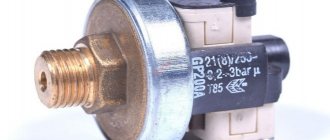
- We start checking with fuse 2 and posistor 3. Then we call the diode bridge, resistors, transistors and the microcircuit (if a high-voltage stabilizer is installed).
- If everything is in order, install new elements instead of old ones.
When replacing parts, especially transistors and microcircuits, be sure to install gaskets (mica or rubber) if they were installed under the housings of these elements. They serve to isolate components from the housing.
Remember! In case of any problems with the power supply, it is better to replace its main element (high-voltage transistor or stabilizer chip).
Repair of LCD/LCD TVs
There are two options for the location of the power supply in such devices:
- Internal . It may be located in such a place that sometimes it is necessary to disassemble the entire television monitor. For example, many Chinese models do not have screws that secure the cover. To repair them, you need to pry off the plastic case with a flat tool (screwdriver) and remove the screen with the video driver, followed by the metal casing. By removing (unscrewing) it, you will get to the power supply.
- External . More convenient for repairs, since you don’t have to “get into” the monitor itself.
All these power supplies are similar in operating principle to the power supply of a conventional CRT device, and the method for troubleshooting is the same. The only difference is in the element base and output voltages. Consequently, the repair of plasma TVs and LCD power supply devices is no different from the above.
DIY TV repair photo
Read here - Do-it-yourself kettle repair: principle of operation, design, main types of malfunctions. Step-by-step photo repair instructions. Prevention of breakdowns
Help the site, repost 
0
The LCD/LCD or plasma screen does not light up – there is an image, but it’s barely noticeable
This indicates a problem in the backlight circuit. There are two reasons for this:
- Fixtures (lamps or LEDs) are damaged.
- There is no power supply to the backlight (backlight generator, transformer, transistors).
If the LCD has a lamp backlight, then the rest have LED backlight.
First option
LCD devices have from 1 to 10 lamps. Rarely do all the lamps burn out at once. In the first case, the lamp itself may be faulty. As a rule, TV sets with other technologies have LED strips installed. In many models they are located in series, and the combustion of one of the LEDs leads to the extinguishing of the entire screen.
Repair of LCD and other TVs is performed as follows:
Step 1 . Open the case.
Step 2 . Remove the driver and power supply boards (they can be located in a metal casing).
Step 3 . Disassemble the screen part. To do this, you need to remove one or two metal casings and (if any) the protective film.
Step 4 . Find backlights or LED strips.
Step 5 . Replace those that do not light up. It doesn’t hurt to check the contacts in the lamps or the diode strip for breaks first visually and with a tester.
Second option
If you have the second case, and all the lights do not light, most likely the problem is in the backlight power supply. LCD equipment uses a high-voltage converter made according to a transformer circuit. Faulty parts (microcircuit or transistors) in its trigger circuit are easily determined by the tester. To do this, measure the voltage on their legs, checking the diagram. If a discrepancy is found, the element is replaced.
But the transformer is difficult to check. Check all voltages (according to the diagram) on the elements of this converter. If everything is normal, the transformer is to blame.
It can be rewound, but this is a hassle, and the quality of such winding will again lead to failure. It’s better to buy a new one (get a working one from a TV workshop) and install it.
In the LED backlight transformer, the potential difference is only 50-100 V. If it is not on the connector, you need to check how many volts are supplied to the transformer. To do this, it is better to remove it. If everything is normal, change the transformer; if not, use a tester to check the remaining elements of the converter.
Can it be repaired?
LCD TVs have become widespread and are installed in many apartments. The popularity of the devices is due to the high-quality images that are suitable for viewing modern content. When wondering whether an LCD display can be repaired, you need to conduct diagnostics and understand the nuances of the TV’s operation.
The main component of the screen is a matrix containing a large number of particles filled with a mixture of xenon and neon. Semiconductors are located along the perimeter of the matrix. During operation of the device, electricity passes through the gaseous medium and produces ultraviolet light, which illuminates the phosphors. Due to this process, individual cells are highlighted in different colors.
All display components are located in a compact space between the planes, which are made from a special type of glass.
When diagnosing a TV screen, you need to determine the type of damage. The most common breakdowns are the following:
- the formation of severe defects provoked by external mechanical influence;
- disruption of the transmitted image due to liquid ingress;
- the occurrence of scratches and microcracks on the surface of the display.
If the screen is severely damaged and the integrity of the matrix is compromised, the gas mixture will begin to escape, and it will be impossible to repair the device. The only way out in this situation is to purchase and replace the matrix. Since the cost of a new matrix is high and comparable to prices for televisions, you should immediately consider purchasing a new device.
Small scratches that do not affect the condition of the matrix can be eliminated yourself. To do this, wipe the surface with a weakly concentrated solution of ethyl alcohol or a special product intended for liquid crystal monitors.
See also
Reasons and what to do if the washing machine fills the tank with water and immediately drains it
No sound or wheezing
In this case, there is a breakdown in the sound path. Check the supply and output voltages on the legs of the audio amplifier microcircuit (with a tester according to the diagram). If they are normal, the piping and input capacitors are to blame.
If nutrition is low or absent, there are two reasons:
- It doesn't come with the PSU . In this case, all elements going from the power supply to the charger are called and the ones that are faulty are replaced.
- The microcircuit is unusable . This can be easily checked by unsoldering the microcircuit. If after this the voltage appears and is normal, it needs to be changed.
The screen lights up, but there is no image
This happens for many reasons. Here are some of them:
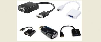
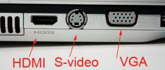
There is no signal from the receiving unit (tuner and its circuits) to the input of the video amplifier . To check, you need to connect some video signal source (computer, VCR, set-top box) to the “Video” sockets on the TV body. For example, HDMI, VGA, tulips (yellow) and others.
If the image appears, the tuner, microcontroller and their circuits are to blame. The microcontroller can be checked quickly. It is responsible for the operation of buttons, input, sound and video signals. If when you press the buttons you can enter the menu and it is displayed on the screen, then the microcontroller is not at fault. Check the potentials on its legs with a tester. If they all match the diagram, change the tuner.
The video processor is to blame . If nothing happens after connecting to the tuners, then check the microcircuit (video processor). Check all supply and output circuits for compliance with the required potentials. If there is a discrepancy, the processor is 70% faulty.
Advice and recommendations from experts
Before you start repairing your TV, you should familiarize yourself with the recommendations of specialists, since in some situations faulty operation is not associated with serious damage. If there is no visual damage to the device and it does not show an image, the problem may be the following:
- No electricity at the outlet. The probable cause is broken circuit breakers in the meter or a planned shutdown.
- Low batteries in the remote control. The TV may be in full working order, but not turn on due to dead batteries. It is worth trying to turn on the TV through the button on the panel to check this option.
- Triggering of the protective relay. The component turns on when there is a sudden change in voltage. A characteristic symptom is the appearance of a black image for a few seconds, after which everything returns to normal.
- Backlight burnout. If the TV does not transmit an image, but sound is heard, it means that the inverter or backlight bulbs have burned out. The problem is solved by replacing components.
- No signal. Malfunctions of the antenna or digital set-top box often lead to the absence of an image on the TV screen.
See also
How to properly connect a gas stove in an apartment, standards for self-installation
Tips and secrets of the masters
- When checking the power supply, turn off the secondary circuits, and instead turn on ordinary light bulbs at the appropriate voltage.
- If you suspect that the “electrolyte” has lost capacity, warm it up with a soldering iron. The electrolyte inside will boil and the capacity will be restored for a short time. The method helps with frame scanning malfunctions, when you can visually see how the screen opens as a result of heating.
- If the high-voltage part is faulty, a slight hissing and crackling noise can be heard. Turn off the lights. In the dark you can tell where the sparks are coming from.