Dosimeters are commonly called devices that are necessary to measure the power of ionizing radiation. It should also be taken into account that some models are additionally capable of assessing the effectiveness of the dose. X-ray meters are not dosimeters. It is pleasant to consider the detector to be the main element of the device. In terms of sensitivity, it differs quite a lot. In general, these devices can be divided into professional and household modifications.
For the military, special models are used that are designed for harsh conditions of use. In turn, industrial modifications are designed for continuous monitoring of radiation. Assembling radiation dosimeters with your own hands is quite simple. However, this only applies to household devices. To make a professional model, you need to study the diagrams of these devices.
Household model in 3 minutes
It is quite simple to assemble a dosimeter with your own hands in 3 minutes. First of all, you should take an eggplant with a capacity of at least 1.5 liters. After this, the device will need a single-pole type tester. First, the eggplant must be cut. For this purpose it is better to use a knife. The next step is to install the tester into the container. Next, to assemble a simple dosimeter with your own hands, a conductor is connected to it.
For this purpose, you will need an open type capacitor. A hole is made in the upper part for the knitting needle. It is best to choose a copper one, with a diameter of no more than 1.2 mm. As a result, the parts of the eggplant must be secured with electrical tape. When the tester is turned on, the signal from the spoke is transmitted to the resistor. As a result, the power of ionizing radiation is displayed on the device.
What is a dosimeter
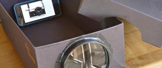
A dosimeter is actually a very simple device, we need a sensitive element, in our case a Geiger tube, power for it, usually about 400V DC and an indicator, in the simplest case it can be a regular speaker. When ionizing radiation hits the wall of a Geiger counter and knocks electrons out of it, it causes the gas in the tube to become a conductor, so a current goes straight to the speaker and causes it to click, if you're interested there is a much better explanation online.
I think everyone will agree that clicks are not the most informative indicator, however, it has the ability to notify about an increase in background radiation, but counting radiation using a stopwatch for more accurate results is a rather strange thing, so I decided to add some brains to the device . A dosimeter is actually a very simple device, we need a sensitive element, in our case a Geiger tube, power for it, usually about 400V DC and an indicator, in the simplest case it can be a regular speaker.
How to make a geiger counter with your own hands.
When ionizing radiation hits the wall of a Geiger counter and knocks electrons out of it, it causes the gas in the tube to become a conductor, so a current goes straight to the speaker and causes it to click, if you're interested there is a much better explanation online. Clicks are not the most informative indicator, however, it has the ability to notify about an increase in background radiation, but counting radiation using a stopwatch for more accurate results is a rather strange thing, so I decided to add some brains to the device.
It will be interesting➡ How to make a power regulator on a triac with your own hands
Two-wire detector device
With a two-wire detector, how to assemble a dosimeter with your own hands? In fact, if you select all the necessary components, then this task is quite feasible. First of all, a container is prepared for the device. As a rule, it is selected as a plastic type. Its dimensions largely depend on the dimensions of the detector. It should also be taken into account that to assemble the model you will need a pass-through capacitor. In turn, three resistors need to be prepared.
Next, to make a dosimeter with your own hands, take a damper. For a model with a two-wire detector, only a single-channel detector is selected. It must be installed directly next to the condenser. Rectifiers for dosimeters of this type are suitable only for resonant ones. In turn, expanders are used by specialists quite rarely. A pass-through capacitor is used directly to measure the dose effectiveness. Additionally, it should be taken into account that the damper in the device must be installed behind the detector.
Applications of three-wire detectors
How to make a three-pass dosimeter with your own hands? It should be noted right away that this task is not easy. Three-pass devices are professional modifications and are designed to measure not only dose efficiency, but also radiation power. It is necessary to install the detector only after all feed-through capacitors have been secured in the housing. In this case, resistors are used only of the closed type.
In turn, the dampers are single-channel. In this case, a low-frequency expander will be required. To measure the radiation power, only resonant rectifiers are used. To install them you will need to use a soldering iron. Zener diodes are used quite rarely in such devices. This is due to the fact that the error in their measurements is high. It should also be taken into account that the radiation power parameter directly depends on the type of output resistor. Most often it is selected electrolytic.
Assembly
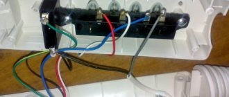
The first thing to do is to adjust the voltage on the high voltage DC-DC potentiometer. For STS-5 we need approximately 410V. Then simply solder all the modules according to the diagram, I used solid wires, this increases the stability of the structure and makes it possible to assemble the device on the table, and then simply place it in the case. The important point is that we need to connect the minus at the input and output of the high-voltage converter, I just soldered the plug.
It will be interesting➡ How to do HDMI pinout
Since we can't just connect the Arduino to 400V, we will need a simple circuit with a transistor, I just soldered them using the hinged method and wrapped them in heat shrink tubing, a 10MΩ resistor from +400V was attached directly to the connector. It is better to make a copper bracket for the tube, but I just wound the wire in a circle, everything works fine, do not change the plus and minus of the Geiger counter. We connect the display with a removable cable, carefully insulating it, since it was located very close to the high-voltage module.
Scheme of a homemade dosimeter.
Dosimeter circuit on a microcontroller
The device is designed to measure ionizing radiation caused by beta and gamma rays and has the following parameters:
- Measured dose range: 0 - 250 milliroentgen/hour
- Supply voltage: 2 – 3.3 V two AA batteries
- Average current consumption: 0.5 mA with sound indication disabled
- Time to reach operating mode: 30 seconds
- Reading update period: 1 second
The device consists of the following functional blocks: a high-voltage generator for powering the gas-discharge counter, a counter pulse shaper, a liquid crystal display control unit, an audio indication unit, and voltage stabilizers for powering various circuits of the device.
Synchronous control of all blocks is provided by the DD2 microcontroller. The high voltage is generated by the converter on transistor VT2 and transformer T1. The VT2 gate receives pulses with a frequency of 244 Hz and a duty cycle of approximately 4-15% from the DD2 microcontroller. At the moment of the pulse, the transistor is open and magnetic energy accumulates in the magnetic circuit T1.
Diagram of a homemade radiometer.
When the transistor is closed, a self-induction EMF is formed in winding I of the transformer, leading to a short pulse of positive polarity with an amplitude of about 60 V at the drain of VT2. This voltage is increased by winding II and supplied to the voltage tripler on diodes VD3-VD5 and capacitors C12-C14. The use of a voltage tripler reduces the requirements on the transformer and simplifies its design. A high voltage of about 400 V is supplied to the Geiger counter BD1 through load resistor R10.
Expert commentary
Lagutin Vitaly Sergeevich
Engineer with a degree in Computer Software and Automated Systems, MEPhI, 2005–2010.
Ask a Question
At this voltage, the meter operates in the middle of the plateau of its operating range. Zener diodes VD6-VD8 limit the voltage at the tripler output to a level of 430 V and protect capacitors C11-C13 with a rated operating voltage of 630 V from breakdown. Such protection is necessary during the setup process or when the dosimeter is suddenly removed from the radiation source.
Without zener diodes, the voltage on the capacitors can exceed 800-900 V and lead to their breakdown. The average current consumption in the T1-VT2 circuit does not exceed 0.3 mA with a load resistance of 40 MOhm and higher.
Using Vector Resistors
You can assemble a dosimeter with vector resistors with your own hands (the diagram is shown below) only in conjunction with network detectors. Today it is quite difficult to purchase them in a store. It should also be taken into account that this product costs a lot these days compared to other types of detectors. It is necessary to install resistors only after securing the feed-through capacitor. In some models, two units are soldered. In this case, the negative resistance of the circuit can sometimes reach 30 ohms. In this case, the measurement accuracy suffers significantly. Also, the operating error of the device can be affected by the capacitance of the capacitors. Most often they are selected at 20 pF. All this is enough to provide the model with excellent sensitivity.
Next, to make a dosimeter with your own hands, install a rectifier. In this case it is suitable for the resonant type. However, positional models are also considered by many specialists. At this stage, it is very important to calculate the electromagnetic interference parameter. To reduce environmental impact, many experts recommend installing electrostatic blocks in devices. You can buy them in the store quite easily. It is also possible to use a low power trigger. However, in this situation, the negative resistance in the dosimeter can increase sharply. To prevent frequency shifts from occurring frequently, it is more advisable to use integrated triggers.
Application of integral resistors
You can make a simple dosimeter with integrated resistors with your own hands (the diagram is shown below) very quickly. First of all, for this you will need to select a case. In this case, you can use a plastic box. Next, to make a dosimeter with your own hands, you need to install a damper. Most often it is selected as a multi-channel type. In turn, single-channel models do not provide high accuracy readings.
It should also be noted that many experts recommend using meters. As a rule, they are selected binary type. They must be installed directly on the detector. In this case, the capacitors are soldered after the resistors. A total of three units are required for the dosimeter. The first of them is installed directly on the detector. Its sensitivity depends largely on the type of expander. The remaining two capacitors are mounted on the outside of the rectifier. To do this you will have to use a blowtorch.
List of parts needed for the radio circuit
- 1 BPW34 photodiode
- 1 LM358 op amp
- 1 transistor 2N3904
- 1 transistor 2N7000
- 2 capacitors 100 NF
- 1 capacitor 100 µF
- 1 capacitor 10 nF
- 1 capacitor 20 nF
- 1 10 MΩ resistor
- 2 1.5 Mohm resistor
- 1 56 kohm resistor
- 1 150 kohm resistor
- 2 1 kohm resistor
- 1 250 kohm potentiometer
- 1 Piezo speaker
- 1 Power switch
As you can see from the diagram, it is so simple that it can be assembled in a couple of hours. After assembly, make sure the polarity of the speaker and LED are correct. Place copper tubes and electrical tape on the photodiode. It should fit snugly. Drill a hole in the side wall of the aluminum case for the toggle switch, and on top for the photosensor, LED and sensitivity control.
It will be interesting➡ How to make a Kharchenko antenna for T2 with your own hands
Interesting read: How to make a motion sensor with your own hands.
There should be no more holes in the case, since the circuit is very sensitive to electromagnetic interference. Once all electrical components are connected, insert the batteries. We used three CR1620 batteries stacked together. Wrap electrical tape around the tubes to prevent them from moving.
This will also help block light from reaching the photodiode. Now everything is ready to begin detecting radioactive particles. You can check it in action on any test radiation source, which you can find in special laboratories or in school classrooms for practical work.
A simple model based on the PP20 transistor
It is not easy to assemble this type of radiation dosimeter with your own hands, but it should be understood that the detector in this case is only suitable for the pulse type. The transistor must be installed on the rectifier. Extenders for these purposes are selected mainly of the analog type. All this is necessary in order to more accurately measure the radiation power. Among other things, it is important to choose a high-quality meter for the dosimeter. Most often it is used with a segment indicator. The most common modifications are sold in stores labeled K17. LEDs are used quite rarely for devices of this type. In turn, testers can only be installed of the low-frequency type. However, their sensitivity is quite low.
Using the PP30 transistor
Transistors of this type are usually installed on professional models. Their conductivity is quite good, but they can only work with two-wire detectors. To assemble a dosimeter with your own hands, first of all you need to make a housing for the device. After this, it is standardly necessary to select a high-quality feed-through capacitor for the dosimeter.
Its minimum capacitance should be 40 pF. All this is necessary to ensure that the negative resistance in the circuit is maintained at 20 ohms. Frequency shifts in this case can be controlled using a rectifier. To measure the radiation power, a conventional damper is used. Transistor P30 can be installed only after fixing the expander. Emitter zener diodes are often used, but they are poorly suited for determining dose effectiveness.
Model with membrane capacitor
Membrane-type devices are quite common today. Compared to camping capacitors, they are characterized by reduced sensitivity. In this case, the negative resistance in the circuit is usually no more than 3 ohms. All this suggests that the accuracy of determining the radiation power of such devices is quite high. It should also be taken into account that the detectors in this case are only suitable for the two-wire type. In general, the models are compact, but their characteristics are quite different. Expanders for such capacitors are suitable of the electrostatic type. In turn, rectifiers are used both analog and resonant.
However, to increase the accuracy of the readings, many experts advise choosing the second option. Triggers for these dosimeters are suitable for medium power. It should also be taken into account that zener diodes are used in devices quite rarely. In this case, dampers to increase sensitivity must be installed with two resistors.
Using broadband capacitors
Broadband modifications are quite rare today. Their sensitivity is not the best. It should also be taken into account that they are not able to determine the radiation power. Detectors are most often selected as a three-pass type for devices. Thus, in terms of dimensions they are quite large. Dampers are installed on a wide variety of dosimeters. To improve the accuracy of readings, multi-channel modifications are often used. The frequency of electromagnetic interference in this case depends on the class of the rectifier. Many specialists purchase them with low throughput.
Most often they can be found labeled MP30. Additionally, modifications of the MP40 class are known. Their input response is quite high, but they can withstand low negative resistance. Capacitors should be installed on the device only after fixing the detector itself. It should also be taken into account that three resistors are required for the circuit. The first of them should be soldered at the beginning of the circuit. In this case, the remaining two resistors are needed at the expander.
Its main characteristics of the dosimeter:
| Emission spectrum | b(>0.5 MeV), g(>0.05 MeV) |
| Reaction to natural background radiation (ERF) | acoustic pulses-clicks, following with an average frequency of 15...25 imp/min; |
| Response to changes in radiation levels | change in counting rate (linear dependence); |
| Alarm threshold | 4…5 ERF |
| Power supply voltage | 9 V |
| Current consumption: in background radiation fields in alarm mode | 0.15…0.2 mA3…4 mA |
| Continuous operation time (with Corundum battery) | >5000 hours |
| Time to reach operating mode | <1c |
| Device dimensions | 120x46x21 mm |
| Device weight (with power supply) | 100 g |
The schematic diagram of the dosimeter is shown in Fig. 1. The BD1 sensor is a Geiger counter type SBM20. The blocking generator creates a high voltage at its anode - from the step-up winding I of transformer T1, voltage pulses through diodes VD1, VD2 charge the filter capacitor C1. Resistor R1 serves as a counter load, connected to input 8 of the DD1 chip.
Transistor tester / ESR meter / generator
Multifunctional device for testing transistors, diodes, thyristors...
More details
A single-vibrator assembled on elements DD1.1, DD1.2, SZ and R4 converts the pulse coming from the Geiger counter and having a prolonged decay into a rectangular one with a dimension of 5...7 ms. Using elements DD1.3, DD1.4, C4 and R5, a sound generator controlled by input 6 of DD1 is assembled. The threshold amplifier, made on the DD2Na chip, is controlled by an integrator using elements VD4, R8...R10, C8 and C9.
The voltage on capacitor C9 depends on the excitation frequency of the Geiger counter; when it reaches the unlocking potential of the transistor included in DD2, the HL1 LED turns on: the blinking frequency will increase with increasing radiation level.
Transformer T1 is wound on a ring core M3000NM of standard size K16x10x4.5 mm. The sharp edges of the core are sanded down and the core is covered with electrically and mechanically strong insulation, for example, wrapped with electrical tape. Winding I contains 420 turns of PEV-2-0.07 wire. The winding is led almost turn to turn, in one direction, leaving a gap of 2 mm between its beginning and end.
This winding is also covered with insulation. Next, winding II is wound - 8 turns of wire with a diameter of 0.15...0.2 mm in any insulation, and winding III - 3 turns of the same wire is wound on top of it. It is necessary to distribute these windings evenly across the core. The location of the windings and their terminals must correspond to the drawing of the printed circuit board, and their phasing - indicated on the circuit diagram (the in-phase ends of the windings are indicated by dots). The assembled transformer must be covered with a layer of waterproofing - wrapped, for example, with a narrow strip of adhesive tape.
Low sensitivity dosimeter
Low sensitivity dosimeters are most often used by the military. To assemble a model of this type, you must first select a high-quality sensor. In this case, counters are most often used with segment indicators. In turn, capacitors for such modifications are more suitable of the pass-through type. Many experts recommend purchasing analog resistors.
All this is necessary in order to increase the sensitivity of the device to the desired level. Triggers in models are most often used with low power. They must withstand a maximum negative resistance of 4 ohms. In this case, the sensor itself must be designed for 5 ohms. The speed of the output signal depends solely on the power of the capacitor. There are no dampers in devices of this type.
Description of the operation of the dosimeter on the Geiger counter SBM-20
The dosimeter circuit is powered by just one 1.5 volt battery, since the current consumption does not exceed 10 mA. But since the operating voltage of the SBM-20 radiation sensor is 400 volts, a voltage converter is used in the circuit to increase the voltage from 1.5 volts to 400 volts. In this regard, extreme caution should be observed when setting up and using the dosimeter!
Board holder
Material: ABS + metal, PCB clamp size (max): 20X14cm...
More details
The dosimeter boost converter is nothing more than a simple blocking generator. The high voltage pulses that appear on the secondary winding (pins 5 – 6) of transformer Tr1 are rectified by diode VD2. This diode must be high-frequency, since the pulses are quite short and have a high repetition rate.
If the Geiger counter SBM-20 is outside the radiation zone, there is no sound or light indication, since both transistors VT2 and VT3 are locked.
When beta or gamma particles hit the SBM-20 sensor, the gas located inside the sensor is ionized, as a result of which a pulse is formed at the output, which is sent to the transistor amplifier and a click is heard in the BF1 telephone capsule and the HL1 LED flashes.
Outside the zone of intense radiation, LED flashes and clicks from the telephone capsule follow every 1…2 seconds. This indicates normal, natural background radiation.
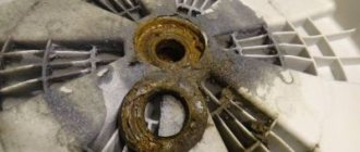
When the dosimeter approaches any object with strong radiation (the scale of a wartime aircraft instrument or the luminous dial of an old watch), the clicks will become more frequent and may even merge into one continuous crackling sound; the HL1 LED will be constantly on.
The dosimeter is also equipped with a dial indicator - a microammeter. A trimming resistor is used to adjust the sensitivity of the reading.